Showing posts with label 3d scanners in India. Show all posts

Tuesday, 8 September 2026

How Reverse Engineering Works with Sermoon S1 3D Scanner


Reverse engineering has transformed the way manufacturers, engineers, and product designers recreate existing components. Instead of manually measuring complex geometries and recreating them from scratch, modern 3D scanning technology enables professionals to capture real-world objects and convert them into accurate digital models within hours.

The Sermoon S1 3D Scanner is designed to streamline this process with high-precision scanning capabilities, offering up to 0.02 mm accuracy, advanced blue laser and NIR scanning modes, and compatibility with CAD reconstruction workflows. Whether you’re developing replacement components, redesigning products, or digitizing legacy parts, the scanner helps accelerate the entire reverse engineering workflow.

In this guide, we’ll explore how reverse engineering with a 3D scanner works and how the Sermoon S1 supports the complete process from scanning to manufacturing.

What Is Reverse Engineering?

Reverse engineering is the process of analyzing an existing physical object to understand its design, dimensions, and functionality so that it can be recreated, modified, or improved.

Traditionally, reverse engineering involved manual measurements, drawings, and extensive CAD modeling. While effective for simple components, this approach becomes time-consuming when dealing with complex geometries.

Today, 3D scanning for reverse engineering allows engineers to digitally capture an object’s shape and dimensions with high precision, significantly reducing development time.

Common reverse engineering applications include:

  • Reproducing discontinued spare parts
  • Product redesign and optimization
  • Competitive product analysis
  • Legacy component digitization
  • Quality inspection and validation
  • Manufacturing process improvement

As industries continue adopting digital workflows, industrial reverse engineering has become a critical part of modern product development.

Why Use a 3D Scanner for Reverse Engineering?

A 3D scanner captures millions of data points across an object’s surface, creating a highly detailed digital representation.

Compared to manual measurement methods, reverse engineering with a 3D scanner offers several advantages:

  • Faster Data Collection: Complex parts can be scanned in minutes rather than requiring hours of manual measurement.
  • Improved Accuracy: High-precision scanners capture intricate geometries that would be difficult to measure manually.
  • Reduced Human Error: Automated scanning minimizes inconsistencies associated with traditional measuring tools.
  • Better Product Development: Accurate digital models support faster redesign cycles and engineering validation.

For organizations involved in manufacturing, product development, or maintenance, 3D scanning for reverse engineering improves efficiency while maintaining accuracy.

How the Sermoon S1 Captures Accurate Scan Data

The Creality Sermoon S1 is built specifically for professional scanning applications where precision and reliability are essential.

Key capabilities include:

  • High-Accuracy Scanning: With accuracy up to 0.02 mm, the scanner can capture fine details required for engineering and manufacturing applications.
  • Multiple Scanning Modes: The system utilizes advanced blue laser and NIR scanning technologies to accommodate different surface materials and object types.
  • Efficient Data Acquisition: The scanner rapidly captures large amounts of geometric information, making it suitable for both small components and larger industrial parts.
  • CAD-Friendly Output: Scan data can be exported in formats suitable for CAD reconstruction from scan workflows, enabling seamless integration into engineering software.

These features make the Sermoon S1 3D Scanner a practical solution for companies seeking a reliable scan to CAD process.

Step-by-Step Reverse Engineering Workflow

A successful reverse engineering workflow typically follows several stages.

Step 1: Object Preparation

Before scanning begins, the object is inspected and positioned appropriately to maximize data capture.

Depending on the component, multiple scan angles may be required to capture all surfaces.

Step 2: 3D Scanning

The Sermoon S1 captures detailed surface geometry using laser and optical scanning technology.

During this stage, the scanner generates:

  • Point cloud data
  • Surface geometry information
  • Dimensional measurements

This forms the foundation for the digital model.

Step 3: Scan Alignment

Multiple scans are aligned and merged to create a complete representation of the object.

Accurate scan alignment ensures all captured data fits together correctly.

Step 4: Mesh Generation

After alignment, the software converts the point cloud into a polygon mesh.

This process creates a digital surface representation of the object.

Step 5: Mesh Cleanup and Optimization

The generated mesh is refined through:

  • Hole filling
  • Noise reduction
  • Surface smoothing
  • Mesh optimization

Proper mesh cleanup improves the quality of downstream CAD reconstruction.

Converting Scan Data into CAD Models

One of the most important stages of the scan to CAD process is transforming scan data into editable CAD geometry.

While mesh files accurately represent surface shapes, engineering teams often require parametric CAD models for manufacturing and redesign.

The workflow generally includes:

Point Cloud Processing: Raw scan data is organized and filtered to remove unwanted artifacts.

Surface Extraction: Critical geometric features are identified and reconstructed.

CAD Reconstruction: Engineers create parametric models using the scan data as a reference. This stage is commonly referred to as point cloud to CAD conversion or CAD reconstruction from scan.

Engineering Validation: The reconstructed CAD model is compared against the original scan to verify dimensional accuracy.

The resulting model can then be modified, optimized, or prepared for production.

Creating Replacement Parts with Sermoon S1

One of the most valuable applications of 3D scanning for replacement parts is recreating components that are no longer available from the original manufacturer.

This is particularly useful when:

  • Spare parts are discontinued
  • Original CAD files are unavailable
  • Components have worn out or become damaged
  • Legacy equipment requires maintenance

Using the Sermoon S1, engineers can scan the existing part, reconstruct the geometry, and create a digital model for manufacturing.

Once validated, the part can be produced through:

  • 3D printing
  • CNC machining
  • Injection molding
  • Casting processes

This significantly reduces downtime and accelerates maintenance operations.

For businesses managing aging equipment, reverse engineering old parts has become an increasingly important capability.

Real Industrial Applications of Reverse Engineering

Modern organizations use 3D scanning and modeling across a wide range of industries.

  • Manufacturing: Digitizing existing components for redesign and production optimization.
  • Automotive: Recreating obsolete parts and validating aftermarket components.
  • Aerospace: Capturing complex geometries for maintenance and engineering analysis.
  • Product Development: Accelerating design iterations through accurate digital models.
  • Quality Inspection: Comparing manufactured parts against CAD specifications through dimensional inspection.

These applications demonstrate how industrial reverse engineering supports innovation while reducing development timelines.

Benefits of Using Sermoon S1 for Reverse Engineering

The Sermoon S1 3D Scanner offers several advantages for engineering teams and manufacturers.

  • Improved Accuracy: High-resolution scanning captures fine details required for professional applications.
  • Faster Reverse Engineering: Digital workflows reduce time spent on measurement and modeling.
  • Better Product Redesign: Accurate scan data enables more effective design modifications.
  • Reduced Development Costs: Minimizing manual work lowers engineering effort and project timelines.
  • Greater Manufacturing Flexibility: Digital models can be used across multiple production methods and workflows.

For companies seeking a high accuracy 3D scanner capable of supporting product development, spare-part reproduction, and manufacturing workflows, the Sermoon S1 provides a practical and efficient solution.

Conclusion

Modern 3D scanning for reverse engineering has significantly simplified the process of recreating and improving physical products. By capturing highly accurate scan data and converting it into editable CAD models, organizations can accelerate product development, reduce downtime, and improve manufacturing efficiency.

The Sermoon S1 3D Scanner supports every stage of the reverse engineering workflow, from data capture and mesh processing to CAD reconstruction and final production. Whether you’re creating replacement components, redesigning products, or digitizing legacy parts, the scanner provides the precision and flexibility needed for professional engineering applications.

As industries continue to embrace digital manufacturing, tools like the Sermoon S1 are becoming essential for efficient and accurate reverse engineering projects.

Frequently Asked Questions

Q. What is reverse engineering with a 3D scanner?

Ans: Reverse engineering with a 3D scanner involves capturing the geometry of a physical object and converting the scan data into a digital model that can be analyzed, modified, or manufactured.

Q. How does the scan to CAD process work?

Ans: The process includes scanning the object, generating a point cloud, creating a mesh, reconstructing CAD geometry, and validating the final model for manufacturing or design purposes.

Q. Can the Sermoon S1 be used for replacement-part development?

Ans: Yes. The Sermoon S1 is commonly used to digitize existing components and create accurate CAD models for replacement-part production.

Q. What file formats are used in reverse engineering workflows?

Ans: Most workflows use point cloud, mesh, STL, OBJ, and CAD-compatible formats depending on the reconstruction software and manufacturing requirements.

Q. Why is 3D scanning important for product redesign?

Ans: 3D scanning provides accurate digital representations of existing products, enabling engineers to analyze, improve, and modify designs more efficiently.

Monday, 7 September 2026

3D Scanning for Reverse Engineering: Complete Guide


Reverse engineering proves invaluable across industries from manufacturing and aerospace to healthcare and consumer products. However, traditional measurement methods consume significant time and introduce human error. 3D scanning for reverse engineering transforms how engineers digitize physical objects into accurate digital models. Consequently, companies reduce project timelines by 40–60% while improving precision dramatically.

This complete guide walks you through 3D scanning technologies, workflows, real-world applications, and best practices. Whether you’re retrofitting legacy equipment or innovating new designs, understanding 3D scanning fundamentals accelerates your engineering process. Moreover, you’ll discover how to select the right scanning solution for your specific reverse engineering needs.

What Is 3D Scanning for Reverse Engineering?

3D scanning captures the physical dimensions and geometry of existing objects, converting them into digital models. Meanwhile, reverse engineering analyzes these digital models to understand design intent, materials, and manufacturing processes. Together, these technologies enable engineers to recreate, modify, and improve existing products.

Therefore, 3D scanning eliminates manual measurement challenges. The technology creates accurate point clouds collections of 3D coordinates representing object surfaces. Subsequently, these point clouds transform into CAD models usable in design software, simulation tools, and 3D printing applications.

The process accelerates design cycles significantly. Furthermore, it preserves institutional knowledge when engineers retire or move to new positions. Equally important, 3D scanning reduces reverse engineering costs compared to traditional destructive testing methods.

Primary 3D Scanning Technologies for Reverse Engineering

Structured Light Scanning

Structured light projectors emit patterns onto object surfaces, and cameras capture distortions. As a result, the system calculates precise surface geometry. This technology excels at capturing fine details and complex geometries.

Advantages:

  • High accuracy (±0.05mm achievable)
  • Fast data acquisition
  • Excellent for detailed features
  • Ideal for small-to-medium parts

Limitations:

  • Struggles with reflective surfaces
  • Requires controlled lighting environments
  • Limited working range

Laser Triangulation Scanning

Laser beams project onto surfaces while cameras measure reflection angles. Accordingly, the system triangulates 3D positions with exceptional precision. This method proves particularly effective for industrial applications.

Advantages:

  • Extreme accuracy (±0.01mm range)
  • Works on reflective and translucent materials
  • Portable scanning solutions available
  • Real-time data processing

Limitations:

  • Slower acquisition than structured light
  • Cannot scan transparent materials effectively
  • Requires careful calibration

Photogrammetry and AI-Powered Scanning

Modern photogrammetry uses multiple 2D photographs and AI algorithms to reconstruct 3D models. In addition, smartphone-based solutions now deliver professional-grade results at minimal cost. This democratization has revolutionized accessibility to scanning technology.

Advantages:

  • Lowest equipment cost
  • Minimal setup requirements
  • Works with existing cameras
  • Flexible working environments

Limitations:

  • Lower accuracy than laser methods
  • Requires good lighting and texture
  • Longer processing times

The Complete 3D Scanning Reverse Engineering Workflow

Step 1 -Part Preparation and Planning

First, carefully examine your physical part. Identify critical features requiring precise measurement. Next, mark reference points and establish a coordinate system. This preparation prevents measurement errors downstream.

Additionally, evaluate surface conditions. Reflective or transparent areas may require temporary coatings to enable accurate scanning. Plan your scanning angle to capture all necessary details.

Step 2 -Scanning and Data Acquisition

Begin by calibrating your 3D scanner according to manufacturer specifications. Then, position your part within the scanning volume. Subsequently, acquire multiple scan passes from different angles.

Meanwhile, monitor point cloud quality in real-time. Adjust lighting, scanner positioning, or part orientation if gaps appear in data. Finally, export your complete point cloud in standard formats (STL, OBJ, PLY).

Step 3 -Data Processing and Cleanup

After scanning concludes, raw point cloud data requires cleanup. Therefore, remove noise, outliers, and unwanted background points. Moreover, align multiple scans into a single unified point cloud.

This step demands precision and patience. Consequently, professionals invest 20–30% of project time here. However, thorough cleanup produces superior CAD models downstream.

Step 4 - CAD Model Generation

Subsequently, convert your cleaned point cloud into a polygon mesh (STL format). Afterward, refine this mesh -filling holes and smoothing surfaces. Then, create solid CAD models using reverse engineering software.

At this point, your digital model matches your original part with measurable accuracy. Finally, validate dimensions against original specifications using quality control procedures.

Step 5 -Model Validation and Application

Before finalizing, measure critical dimensions in your CAD model. Compare these measurements against original parts. Ensure tolerances fall within acceptable ranges.

Once validated, your model becomes ready for multiple applications — design modification, manufacturing, simulation analysis, or 3D printing production runs.

Real-World Applications of Reverse Engineering with 3D Scanning

Manufacturing and Production: Companies reverse engineer competitor products to understand design strategies. Moreover, manufacturers digitize legacy equipment lacking CAD documentation.

Aerospace and Defense: Complex turbine blades and aircraft components require precise 3D scanning. Thus, engineers ensure continued production of replacement parts decades after original manufacturing.

Medical Device Development: Dental labs scan patient models for custom prosthetics. Meanwhile, orthopedic manufacturers create personalized implants matching individual anatomy.

Automotive Restoration: Classic car enthusiasts digitize original parts. Consequently, reproduction parts match originals with exceptional accuracy. Additionally, designers analyze aerodynamic features of iconic vehicles.

Consumer Products: Product designers evaluate competitor solutions. Furthermore, engineers create compatible accessories through reverse-engineered CAD models.

Benefits of 3D Scanning in Reverse Engineering

Reduced Project Timelines: 3D scanning eliminates time-consuming manual measurements. Therefore, projects complete 40–60% faster than traditional methods.

Improved Accuracy: Automated measurements eliminate human error. Consequently, accuracy improves from typical ±2mm manual measurements to ±0.05mm scanner precision.

Cost Efficiency: Non-destructive scanning preserves original parts. Meanwhile, companies avoid expensive replacement costs associated with destructive testing.

Design Preservation: Digital records preserve engineering knowledge. Thus, companies protect critical information regardless of employee turnover.

Enhanced Collaboration: Digital models enable seamless collaboration between distributed teams. Furthermore, engineers worldwide access identical CAD data simultaneously.

Selecting Your 3D Scanning Solution

Consider these critical factors:

  1. Required Accuracy: Tolerance needs dictate scanner selection. Laser scanners suit high-precision applications (±0.01mm), while photogrammetry satisfies general engineering (±0.1mm).
  2. Part Complexity: Intricate geometries favor structured light. Conversely, simple shapes scan effectively via photogrammetry.
  3. Budget Constraints: Smartphone photogrammetry costs $0–500. Meanwhile, industrial-grade laser scanners range $50,000-$500,000+.
  4. Working Environment: Reflective parts require specific technologies. Accordingly, assess ambient lighting conditions at your facility.
  5. Turnaround Requirements: Real-time scanning needs demand structured light. Alternatively, photogrammetry works when processing delays are acceptable.

Best Practices for Successful Reverse Engineering Scans

Optimize Surface Preparation: Apply temporary matte coatings to reflective surfaces. This simple step dramatically improves scan quality.

Establish Reference Points: Mark known dimensions on your part. Subsequently, validate scanner accuracy against these references.

Plan Multiple Scan Angles: Capture parts from minimum 8–12 different perspectives. Consequently, you eliminate data gaps and improve point cloud completeness.

Use Professional Software: Invest in quality point cloud processing software. Therefore, post-processing demands significantly decrease.

Validate Early and Often: Check intermediate results throughout your workflow. Thus, you catch and correct errors before completing lengthy processing steps.

Document Your Process: Record scanner settings, environmental conditions, and processing parameters. Subsequently, this documentation enables consistent results across multiple projects.

Common Challenges and Solutions

Challenge: Reflective or transparent surfaces preventing accurate scanning. Solution: Apply temporary matte coatings (spray powder or paint). Afterward, remove these coatings without damaging original parts.

Challenge: Incomplete point clouds with missing surface areas. Solution: Increase scanning angles from 8 to 12+ perspectives. Additionally, improve lighting and surface preparation.

Challenge: Excessive processing time for CAD generation. Solution: Use automated mesh generation algorithms. Meanwhile, invest in faster computing hardware for parallel processing.

Challenge: Dimensional discrepancies between scanned model and original part. Solution: Validate using coordinate measuring machines (CMM). Subsequently, adjust scanner calibration or post-processing parameters.

Future Trends in 3D Scanning Technology

AI-Powered Automation: Machine learning algorithms accelerate mesh generation. Therefore, processing times decrease from hours to minutes.

Mobile Scanning Solutions: Handheld scanners increasingly compete with fixed systems. Consequently, on-site scanning becomes more accessible to smaller manufacturers.

Real-Time Quality Feedback: Advanced systems now display scanning quality during acquisition. Thus, engineers optimize results immediately rather than discovering problems later.

Hybrid Approaches: Combined technologies leverage individual strengths. For instance, structured light captures detail while photogrammetry covers large areas economically.

CONCLUSION

3D scanning for reverse engineering revolutionizes how engineers digitize physical objects into usable CAD models. From structured light and laser triangulation to AI-powered photogrammetry, multiple technologies serve different accuracy and budget requirements.

The five-step workflow preparation, scanning, cleanup, CAD generation, and validation ensures consistent quality outcomes. Moreover, real-world applications span manufacturing, aerospace, medical devices, automotive, and consumer products.

By selecting appropriate technology for your needs, managing your workflow carefully, and following best practices, you’ll achieve faster project timelines, superior accuracy, and significant cost savings. Start your reverse engineering project today with confidence in proven 3D scanning processes.

Ready to digitize your physical parts? Explore our recommended 3D scanning solutions and CAD generation tools. Download our free reverse engineering checklist to guide your next scanning project -simply subscribe to our newsletter and access exclusive resources.

FAQs

Q1: How accurate is 3D scanning for reverse engineering compared to manual measurement?

A: 3D scanning dramatically outperforms manual methods. Laser scanners achieve ±0.01–0.05mm accuracy compared to ±2mm typical manual measurement tolerances. This represents 20–200x improvement in precision. Additionally, automated scanning eliminates human variability entirely. The technology scales this accuracy across entire parts consistently, whereas manual measurements introduce increasing errors on larger or more complex geometries.

Q2: Can 3D scanning work on reflective or transparent materials?

A: Reflective materials present challenges but prove manageable. Temporary matte coatings (powder spray or removable paint) enable accurate scanning without damaging original parts. Meanwhile, laser triangulation scanners handle reflective surfaces better than structured light systems. However, transparent materials like glass or clear plastic resist scanning due to light refraction. Solutions include coating techniques or alternative technologies like CT scanning for internal geometry analysis.

Q3: How long does reverse engineering a complex part typically require?

A: Timeline varies considerably based on complexity and accuracy requirements. Simple geometric parts might scan, process, and generate CAD in 2–4 hours. Conversely, highly complex components with intricate features may require 2–5 days. The workflow typically breaks down as: 30% scanning and preparation, 40% data processing and mesh generation, 30% CAD modeling and validation. Therefore, plan 1–3 weeks for industrial-grade projects involving rigorous quality control.

Tuesday, 1 September 2026

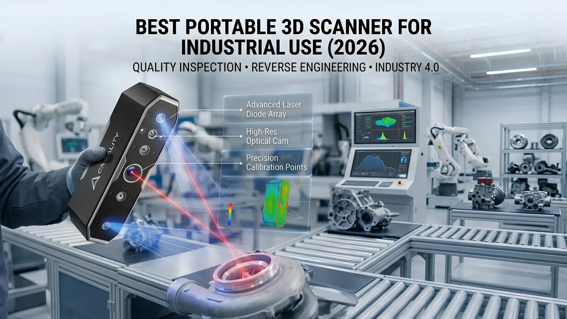
Best Portable 3D Scanner for Industrial Use (2026)


Best Portable 3D Scanner for Industrial Use (2026)

Best Portable 3D Scanner for Industrial Use (2026)

Industrial environments demand three things from every measurement system: accuracy, speed, and adaptability. Fixed metrology systems deliver on the first two but fail on the third. That’s why portable 3D scanners have become the go-to choice for modern factories, reverse engineering labs, and field inspection teams.

This guide compares the top handheld 3D scanner technologies of 2026, breaks down which is best for which industrial application, and helps you select the right machine for your workflow.

Quick Comparison: Top Portable 3D Scanner Categories

Scanner Type

Accuracy

Speed

Price Range

Best For

Structured Light Scanner

High

Fast

Medium

Small parts, quality inspection

Laser Handheld Scanner

Very High

Medium

High

Large objects, industrial environments

Hybrid Scanner

High

High

Premium

Mixed workflows, advanced industrial

Use this as a starting frame, then read on for the detail on each category.

Why Industries Need Portable 3D Scanners

The traditional alternative fixed coordinate measuring machines (CMMs) or studio-based scanners has three drawbacks for modern production:

  • Parts must come to the scanner, which means transport, fixturing, and downtime

  • Limited adaptability to varied part sizes and geometries

  • High capex for single-purpose hardware

A portable 3D scanner inverts the equation. The scanner goes to the part, scans it where it sits, and integrates directly into manufacturing workflows. The result is faster inspection cycles, more flexible reverse engineering, and the ability to capture digital twins of installed equipment without disrupting operations.

This is the foundational technology of Industry 4.0 manufacturing and modern digital quality control.

Top Portable 3D Scanner Categories for 2026

The current market splits cleanly into three technology categories.

1. Structured Light Handheld Scanners

Structured light scanners project a known pattern of light onto the object and calculate depth from how the pattern deforms. Modern systems use blue or white LED light and offer exceptional speed-to-accuracy ratios.

Pros:

  • High accuracy at small to medium part sizes

  • Fast scan rates, ideal for production inspection

  • Excellent for capturing fine detail

  • Often the most affordable handheld option

Cons:

  • Struggle with reflective or transparent surfaces (requires matte spray)

  • Limited performance on very large objects

  • Sensitive to ambient lighting

Best for: small-to-medium part inspection, dental and medical applications, art and heritage digitisation, and detailed reverse engineering of consumer products.

2. Laser Handheld Scanners

Laser scanners project one or more laser lines that sweep across the object. Modern systems use multiple lasers simultaneously, dramatically increasing capture speed.

Pros:

  • Industry-leading accuracy for handheld systems

  • Excellent for large parts and assemblies

  • Work well in challenging lighting (factory floors, outdoor sites)

  • Better performance on dark and slightly reflective surfaces

Cons:

  • Higher cost than structured light

  • Slightly slower capture rates for fine detail

  • Typically heavier and larger

Best for: large-scale reverse engineering, automotive and aerospace inspection, heavy machinery, and on-site industrial work.

3. Hybrid Portable Scanners

Hybrid scanners combine multiple sensing modes typically structured light for fine detail plus laser lines for larger features in a single device. This makes them the most versatile category, though also the most expensive.

Pros:

  • Single device handles small parts and large assemblies

  • Excellent accuracy across the range

  • Adaptive to different surfaces and lighting

Cons:

  • Premium pricing

  • Steeper learning curve due to multiple capture modes

  • Larger software ecosystem to manage

Best for: professional reverse engineering shops, large industrial users with varied scanning needs, and service providers handling diverse client projects.

Handheld vs Stationary 3D Scanner

A practical decision frame for industrial use:

Handheld scanners offer mobility, faster setup, and the ability to scan parts in their installed location. They are ideal for field inspection, on-site reverse engineering, and any workflow where moving the part is impractical.

Stationary scanners (CMMs, optical CMMs, blue-light booth systems) offer slightly higher accuracy and repeatability for parts that can be brought to them. They excel at high-throughput inspection of identical parts in a controlled environment.

Most modern industrial operations now use both stationary systems for production-line QA, handheld systems for reverse engineering, repair, and field inspection.

Structured Light vs Laser Handheld 3D Scanner

A common buyer dilemma. The decision framework:

  • Scanning small parts with fine detail ? Structured light

  • Scanning large parts or assemblies ? Laser

  • Working in variable lighting conditions (factory floor, outdoor) ? Laser

  • Need maximum accuracy at small scale ? Structured light

  • Need maximum versatility ? Hybrid

Both technologies have matured to the point that either delivers professional results for the right application. The wrong technology for your application is the most expensive mistake you can make.

Features to Look For in a Portable 3D Scanner

Whichever category you choose, the features that matter:

  • Accuracy and resolution -published as volumetric accuracy and point spacing. Look for accuracy at the micron level for engineering applications.

  • Capture speed -measured in points/second. Higher speeds shorten scan time, especially for large parts.

  • Portability -weight, battery life, and wireless operation matter for field work.

  • Software ecosystem -make sure the scanner’s software integrates with your CAD and metrology toolchain (Geomagic, PolyWorks, etc.).

  • Object size range- confirm the scanner covers your typical part envelope, with margin.

  • Surface adaptability -modern scanners handle most surfaces, but verify performance on the materials you’ll actually be scanning.

  • Service and calibration support in India.

Get all of these right and you have a scanner that pays back its investment in months.

How to Choose a Portable 3D Scanner for Industry

A practical buying process:

  1. Define your primary use case. Reverse engineering, quality inspection, on-site digitisation? Each suggests different technologies.

  2. Define your typical part size. Sub-300 mm parts favour structured light; multi-metre objects favour laser.

  3. Define your accuracy threshold. Aerospace and medical demand 10–50 micron volumetric accuracy; consumer reverse engineering tolerates 100+ micron.

  4. Define your throughput. One part a day vs 50 parts a day changes the right answer.

  5. Define your software workflow. Choose a scanner whose software fits cleanly into your existing pipeline.

  6. Compare total cost of ownership. Include software, training, calibration, and accessories not just hardware sticker price.

A scanner is a multi-year investment. Spending an extra week on the decision saves months of regret.

Challenges in Industrial 3D Scanning

Honest about the limits:

  • Reflective surfaces still cause headaches. Matte spray, polarising filters, or laser scanners help.

  • Dark surfaces absorb light and scan poorly. Most laser scanners cope better than structured light.

  • Very large objects demand multi-scan workflows with careful alignment.

  • Data volumes are huge -plan for adequate storage, RAM, and GPU compute for processing.

None of these are deal-breakers. They are simply factors to plan for.

How to Improve Accuracy in 3D Scanning

Practical accuracy tips:

  • Calibrate the scanner before every important session

  • Maintain consistent scan distance per the manufacturer’s spec

  • Use physical reference markers (or photogrammetry targets) for large objects

  • Capture in stable, indirect lighting where possible

  • Use matte spray on reflective surfaces

These steps compound. Each one adds a few percent of accuracy; together they decide whether the final model passes engineering acceptance.

Use Cases for Portable 3D Scanners

Where these scanners deliver the most value:

  • Automotive -reverse engineering legacy parts, inspecting body panels, validating tooling

  • Aerospace -first-article inspection, complex geometry validation, repair scanning

  • Tooling and manufacturing -design validation, jig and fixture scanning

  • Heritage and museums -digital archiving of artefacts

  • Healthcare and medical devices -custom prosthetics, orthotics, surgical planning

  • Construction and infrastructure -as-built BIM scanning, deformation analysis

Each of these has been transformed by portable scanning over the past five years.

Portable 3D Scanning Limitations and Solutions

No technology is universal. The current limits:

  • Surface limitations ? use matte spray, polarised lighting, or hybrid scanners

  • Size limitations ? multi-scan workflows with careful alignment, or photogrammetry hybrid

  • Operator skill ? invest in formal training; vendor-led training shortens the curve significantly

  • Data processing time ? invest in adequate workstation hardware (GPU, RAM)

Each limit has a known workaround. The technology landscape is mature enough to support almost any industrial application.

Final Recommendation

The “best” portable 3D scanner depends entirely on your specific application, accuracy threshold, and budget. For most industrial buyers, the decision narrows to:

          High-precision small-part work ? top-tier structured light scanner

          Large parts and field work ? professional laser scanner

          Mixed workflows ? hybrid scanner if budget allows

Explore industrial-grade portable 3D scanners on 3idea Technology: https://www.3idea.in/products/3d-scanner

Choose wisely. The right portable scanner becomes one of the most-used tools in a modern industrial workflow.